Remote Devices
Please refer to the documentation supplied with the units for hardware details and installation instructions.
Connection
Multicast
Discovery of Remote Devices, from Designer or a controller, is achieved using multicast traffic with the 239.192.38.8 multicast group. For this reason, multicast must be available on your network.
TCP/IP
Each remote Device in the system must have an IP Address in the same range as the controllers in the project. This TCP connection is used for all communications with the controller, once the discovery process has been completed using multicast.
The Device table allows you to manage and configure any Remote Devices in the project and found on the network:

Project vs real Remote Devices
The list of Remote Devices is split into two sections: At the top is the list of project devices which may or may not be associated with real devices. Underneath is a list of all the unused real devices found on the network that have not been associated with project devices.
Managing Project Remote Devices
To add and set the type of a project Remote Device:
- Press the New Device button in the toolbar.
- In the New Device dialog, select the device type (RIO 84, RIO 80, RIO 44, RIO 08, BPS, BPI,
- Choose the device's number (on some Remote Devices this is selected on the device itself, see Associating Remote Devices below).
- Choose the device's parent controller.
- Press Add, the Remote Device will be added to the project (and associated to a real device if one of the correct type and address is found on the network).
To delete a project Remote Device:
- Select the project Remote Device by clicking its row, the row will be highlight.
- Press the Delete button in the toolbar.
- The Remote Device will be removed from the project and, if no longer associated at all, the real device will move to the bottom of the device table.
Remote Device firmware
IMPORTANT: Remote Device firmware The embedded operating system, stored in internal flash memory or on the memory card. may need to be updated if a new version of Designer software has been installed. Devices with incompatible firmware will be highlighted in red.
To update a Remote Device's firmware:
- Select the incompatible device by pressing the left hand button, the row will be highlighted.
- Press Reload Firmware on the Remote Device toolbar.
- The firmware update will proceed - you must not disturb this process.
Associating Remote Devices
Unlike Controllers, which are uniquely associated with a project via their serial number, Remote Devices are associated by their address as selected on the unit itself. Automatic addresses 1-15
To associate a project Remote Device with a real device (automatic addresses):
- Select the project Remote Device by clicking the left hand button, the row will highlight.
- Ensure that the device type and number matches a suitable unit, addressed at this number, found on the network.
- The real device will move from the Unused list and fuse with the project device so completing the row details.
To associate a project Remote Device with a real device (manual addresses):
- Ensure that the Remote Device is addressed to the "M" setting, you will need to note its serial number (label on back).
- Select the project Remote Device by clicking the left hand button, the row will highlight.
- Select the correct device type and the desired number.
- Select the Remote Device's serial number from the pull-down menu of devices found on the network.
- The real device will move from the Unused list and fuse with the project device so completing the row details.
Once all your project Remote Devices have been associated with real devices you can configure them, test your programming on the installation itself and finally upload to the Controllers for stand-alone operation.
Remote Input Output (RIO) device properties
Serial Port
The RIO 84, RIO 80, RIO 44 and RIO 08 have a multi-protocol serial port that can be configured to either RS232 full-duplex, RS485 half-duplex, or DMX Out modes. The configuration options are:
- Mode - select RS232, RS485 or DMX Out as required.
The following options are available for RS232 and RS485 modes:
- Baud rate - select the baud rate.
- Data bits - select the number of data bits (typically 8).
- Stop bits - select the number of stop bits.
- Parity - select the parity type.
If DMX Out is selected, the port provides 512 channels of DMX which will subtract from the maximum channel output capacity of the controller. Click 'Create Universe' to create the associated RIO DMX universe in Patch. The button is not shown if the universe already exists.
I/O Configuration
The RIO 84, RIO 80, RIO 44 and RIO 08 differ by virtue of the number and type of I/O ports:
| RIO 84 | Eight inputs, four outputs & serial port |
| RIO 80 | Eight inputs, no outputs & serial port |
| RIO 44 | Four inputs, four outputs & serial port |
| RIO 08 | No inputs, eight outputs & serial port |
Inputs can be individually configured as either Contact Closure, Digital or Analog with the latter two modes allowing for the threshold or range to be selected. Outputs can be individually configured with a Startup state, whether the relay is on or off at startup.
Check the "Check State At Startup" box if you want the inputs to be read and acted upon by triggers at startup.
The "Maintain state on device loss" helps preserve the state of the RIO output relays should the RIO lose its connection to the controller. If this option is checked the RIO will go back to the same state it was in when it was last connected to the controller.
NOTE: The "Maintain state on device loss" feature will work if the RIO device restarts, or if the RIO loses its connection with its controller. However, if the controller restarts then the RIO settings will go back to the default values set within the Project file because the device memory is wiped upon restart.
The Held Timeout is used to set a timeout for the Held event, and the Repeat interval is used to set the interval the Repeat.
See triggers for usage.
Audio
The stereo balanced line level audio input of a RIO A can be used for Audio triggers. Select the Audio button to enable this mode and to see the following configuration options:
- Route To - select the Audio Bus to route the incoming audio to.
- Freq. Bands - select the number of frequency bands with which to analyse the incoming audio (max 30 per channel; the frequency bands sit along a logarithmic scale and have been chosen for an optimum response to music).
- Gain - turn Auto gain on or off, and set the manual gain level.
- Peak Decay Rate - set the rate at which peaks in each frequency band will decay (the peak level can be used in triggers).
- Initially Enabled - the audio feed from a RIO A can be turned on or off by triggers, and here you can set the initial state.
See triggers for usage.
Timecode
The stereo balanced line level audio input of a RIO A can be used for timecode input. Select the Timecode button to enable this mode and to see the following configuration options:
- Channel - the audio input of the RIO A that the timecode input will be connected to.
- Route To - select the Timecode Bus to route the timecode to.
- Regenerate for - select the number of frames that will be generated by the RIO A's software flywheel in the event of a drop in timecode signal.
- Ignore jumps for - select the maximum size of jump in incoming frames that will be ignored.
MIDI
The RIO A has a MIDI input and output interface. This can either be used in Remote Device MIDI triggers, or it can receive MIDI timecode. The configuration options here are for MIDI timecode only:
- Route To - select the Timecode Bus to route the MIDI timecode to.
- Regenerate for - select the number of frames that will be generated by the RIO A's software flywheel in the event of a drop in MIDI timecode signal.
- Ignore jumps for - select the maximum size of jump in incoming frames that will be ignored.
DALI
The RIO D and RIO D4 offer DALI bus interfaces. These interfaces can be used to control DALI ballasts via timeline programming or direct commands or to receive DALI commands for use in DALI Input triggers.
Ethernet Data Node (EDN) / RIO G4 and Serial Data Interface (SDI) device properties
Properties
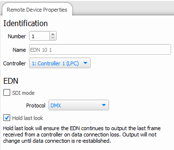
NOTE: Hold last look when active will output at only 5Hz.
SDI
A node can be configured to output via connected SDIs by enabling the SDI checkbox. This will change the Protocols available below.
Protocol
This dropdown will display available protocols of the node. By default, it will offer DMX and UltraDMX, both of which can be connected directly to the node. For other protocols that require the SDI, these options will be displayed once the SDI checkbox has been checked.
Each node can only output one protocol at a time.
Touch Panel Station (TPS) properties
Use these fields to manage the properties of a touch device and its display.
Interfaces for the TPS, TPS 5 and TPS 8 are created on the Interface tab, which is enabled when a relevant Touch Device is added to the project. The Interface dropdown shows all interfaces relevant to the selected device, e.g. a TPS 5 interface won't be shown if a TPS 8 is selected, and vice versa. A new interface can be created by selecting the New... button, or the currently selected Interface can be edited by selecting Edit.
Set the backlight brightness for normal operation and for when the touch device has been inactive for a period of time. The inactivity time is also set here, along with the time before the screen turns off completely.
Set whether the backlight brightness should automatically adjust for changes in the ambient light level, and whether the screen should turn on if the proximity sensor detects someone walking up to it.
NOTE: Proximity detection is not available on TPS 5 or TPS 8.
Button Panel Station (BPS) device properties
Properties
The global properties for each BPS are set here:
- Minimum LED Intensity - set a percentage value as required, useful for ensuring that the buttons are always visible.
- Held Timeout - set the amount of time in milliseconds that a button must be pressed to be considered as being held.
- Repeat Interval - set the interval in milliseconds that a held button will transmit a repeat signal.
Button Configuration
Each BPS has eight buttons with an integral white LED and the default setting for each button is set here:
- Effect - select the default LED effect (Off, Static, Slow Flash etc.).
- Intensity - set the default LED intensity (0% will equal the Minimum LED Intensity as set above).
See triggers for usage and BPS learning IR receiver for infra red operation.